Sometimes it’s not all about throwing the latest bells and whistles at a production facility – its best to keep it simple. Elaine Maslin looks at how an eductor has kept a gas field going.
 |
|
Seajacks’ Kraken working at the DPPA. Images from Centrica. |
Maintaining production from mature assets will always be an interesting challenge. Not least when external influences – a ban in the use of Freon as a refrigerant – causes you to re-route gas to a different terminal, resulting in an increase in back pressure above which one of your fields will no longer flow.
That was the challenge facing Centrica Energy on its North Morecambe Bay field, in the Irish Sea, off the east coast of England. The firm had to re-route gas from the giant South Morecambe field, which had been going to its South Morecambe Terminal, where Freon had been used to cool import gas, via a new underground 1.1km, 36in-diameter trunkline to its North Morecambe Terminal, where a new type of coolant is to be used. This meant back pressure was reduced and production from the North Morecambe field would need compression, or some other way to reduce back pressure for it to flow down the export line to the North Morecambe terminal.
 |
|
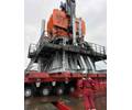
Eductor and Cantilever Sections 4&5. |
The facility producing the North Morecambe field is the North Morecambe or DPPA platform, a 10-well normally unmanned facility, which started production in 1985, and on which it was preferable not to have machinery that would require regular maintenance, such as a compressor. Centrica decided to install an eductor, which go by other names, see below - Overlooked and undervalued section) on DPPA.
Eductors are relatively simple devices that use a high pressure stream to boost a low pressure stream. The Rhyl field, brought on stream in 2013, via DPPA, needed to have its production pressure reduced for export, so it made an ideal high pressure source for an eductor on DPPA.
Rhyl sits at 35 bar g, North Morecambe at 5-6 bar g. Using the high pressure Rhyl flow, the North Morecambe well streams can be increased to above the 8.5 bar g downstream pressure, in the process taking out about 9-10 bar g from the Rhyl stream.
 |
|
Eductor installed. |
“In the process [at North Morecambe] the pipeline pressure from the North Morecambe wells is increased to 8.5 bar g,” says Ronak Patel, project manager. The North Morecambe wells wouldn’t flow downstream otherwise, so this is helping to produce 8.8 Bcf we wouldn’t realize the value of without the eductor.”
Centrica had tried to use an eductor twice previously, but the conditions hadn’t been right. “Eductors have been used elsewhere, but they’ve not necessarily had a 100% record in some applications we’ve used them in,” says Myrtle Dawes, director of projects & decommissioning, Centrica.
Patel says in the past the issue has been not enough understanding around the pressure-flow (P-Q) relationship on new fields, i.e. not knowing enough about how a new field will perform, or uncertainty around the data, so that flow isn’t what was predicted, so the eductor has not been designed correctly.
“In this case, we knew the P-Q relationship on Rhyl and North Morecambe,” which meant the eductor was designed fit for purpose, Patel says. As part of the design, Centrica will also be able to change out the nozzle on the eductor, relatively easily, as the P-Q relationship changes, to match the new regime. This is likely to happen every 2-3 years, Patel says.
Introducing the eductor involved Centrica’s subsurface team and the process team working closely. Just to make life interesting, at that time, Hysys, a process simulation software, didn’t contain a module for modeling eductors, which meant Centrica had to do the modeling itself.
 |
|
Eductor design. |
Then, the 3-tonne eductor package, including nozzle pack, diffuser, and silencers at both ends, on a 17m-long new cantilever structure had to be designed to fit onto a small already busy platform, with pipework for the existing well streams, including Rhyl, also having to be adapted accordingly. In total some 35 spool pieces were installed, as well as a new metering package, at the request of the UK regulator, the Oil and Gas Authority.
The brownfield work made use of a 3D laser scan on the platform, which was used to create a 3D pipeline model, with particular attention paid to key tie-in spools. An animation produced by contractor Amec Foster Wheeler also became a useful tool to show the installation process, from start to finish, through the process.
The project had been approved in February last year, offshore work started in July, using marine contractor Seajack’s Kraken mobile jackup unit. First gas was achieved on 20 September.
And, so far, Centrica is happy with the results. “It is not the most efficient device, but it’s free and it’s efficient enough,” Dawes says. “A few years ago, if we had a bigger flow, we would have put a compressor out there. But, we’ve gone back to basics, getting the same effect, but without the requirements for staff offshore.”
Overlooked and undervalued
 |
Ejectors are also known as eductors, injectors, and surface jet pumps. It’s a technology that has been around since the mid-1800s, says David Ainge, managing director at UK-based Transvac Systems. But it’s been somewhat overlooked and can do more than you might think.
The first US patent for an “oil ejector” was registered in 1866. Since then, ejectors have been commonly used in industries using steam to create a vacuum or liquid for pumping applications.
Transvac Systems has been designing and manufacturing ejectors since it was founded in 1973, mostly for steam and vacuum applications, or liquid ejectors for dosing and mixing. In the 1990s the firm moved into oil and gas, offering a way to boost production on low pressure wells, using otherwise waste energy, including on the southern North Sea Sean field for Shell in 1997. It’s since been offering the technology as part of the sand separation process and has more recently qualified it for subsea applications.
The benefits of ejectors are that they don’t need power and don’t have running costs or maintenance requirements, says Peter Ainge, Transvac’s business development director. They’re also low-weight and compact, he says, making them suitable for brownfield deployment, and make use of an otherwise “waste” product.
Transvac has been designing ejectors for flare gas recovery, since the early 2000s, safely and economically compressing waste and surplus gas back into the production process and reducing emissions.
Since around the same time Transvac ejectors have also been used for pumping sand slurry as part of topside sand separation systems, for clients such as NOV Merpro, Chevron, Maersk Oil Qatar, Total, and BP.
Ainge says take-up hasn’t been as great as it could because of a lack of education about them among those who could them. Transvac is trying to redress that. “Ejector based solutions are a simple, low-cost solutions with CAPEX payback often in a few days,” he says. “However, they are not regarded as the ‘traditional’ solution, so they are not always considered.”
The tide might be turning. “We are seeing an increase in the use of ejectors in two main areas offshore; production boosting/enhanced oil recovery (EOR) and flare gas recovery,” says Gary Short, Transvac’s projects director. “Using ejectors for production boosting provides a low cost method for significantly increasing asset output, typically 20% overall,” he says.
Transvac has also now achieved a fully qualified technology readiness level 7 for subsea ejectors, after providing FMC Technologies and Petrobras each with a fully submersible ejector currently working in depths up to 870m.
More recently, liquid/gas ejectors have been developed for microbubble generation for oil in water separation on compact flotation units.


