 |
|
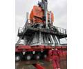
ENI’s Goliat FPSO. Image from ENI Norge. |
Offshore lifting combines heavy offshore assets with detailed analysis and product care. Elaine Maslin found out more at the North Sea Offshore Crane and Lifting Conference.
When it comes to offshore lifting, it is usually the heavy installation vessels and barges that get most of the attention.
But, there is much more to offshore lifting operations, from lift modeling, and crane design and fabrication, to rope manufacture and certification, and rope lubrication and testing. These factors stretch right through project life-cycles and the supply chain, from rope and crane manufacture to design integration and operations.
Norway’s Ship Modelling & Simulation Centre (SMSC) demonstrated how knowing how a rope or crane will perform will be beneficial during front end engineering and design, at the North Sea Offshore Crane and Lifting Conference, held in Aberdeen in late April.
Simulation
SMSC used a crane simulator to improve the crane integration on ENI’s Goliat FPSO, which is due to start production in the Norwegian Barents Sea next year. The simulations, carried out in three phases during design, uncovered blind zones and challenging lift scenarios that were then able to be changed or mitigated.
Torbjorn Alstad, SMSC’s chief marketing officer, told the conference that using the actual design models, SMSC developed simulator models and performed simulated operations for Goliat’s two cranes. This meant blind zones, where the crane operator would not be able to see, lifting corridors, and exhaust zones could be modeled and assessed and changes made to the design before construction started. Certain areas were strengthened, due to being in potential risk of being knocked. Also, which crane corridors would be best utilized for specific tasks were identified.
The changes also meant improvements in the overall design, because it identified extra lay-down area. Where changes could not be made to mitigate an identified problem, alternatives were suggested and adopted, such as focusing on the communication between the crane operator and deck personnel.
 |
|
Lifting operations on the GDF Suez E&P-operated Cygnus development, offshore England, this year. Photo from GDF Suez E&P.
|
“The projects have uncovered blind zones and challenging lifts at a very early stage, enabling us to make necessary changes. It was the first time we had done something like this and I believe more companies should do this type of thing, it would save them a lot of money,” Alstad says.
Slings
Computer modeling could potentially be used to calculate break loads, suggests Jan-Peter Breedeveld, engineering director, Seaway Heavy Lifting, Netherlands. He suggests that few know the actual break load and failure modes in large diameter cable laid slings, which makes defining a safety factor the key challenge.
Wire and fiber slings are used for lifting and can undergo great dynamic loads. Depending on the material, the break load is calculated in different ways. In steel rope slings, the break load in individual wires is measured and then the total rope break load calculated. But there are limited available test facilities, in terms of capacity and length, to test complete steel cable laid slings. Guidance for spliced cable laid slings was also set when the biggest slings were 140mm in diameter—now they are 400mm.
“The failure mode of spliced cable laid sling is not fully understood,” Breedeveld says. “An IMCA sub-group of the crane and winch operations workgroup is working on an update of IMCA M179 and hopefully by the end of the year there will be an updated standard,” he adds. But more tests are needed to better define the design factors in such cable and cutting of core rope or better controlled splicing methods could help, he says. Further, the break load when using alternative terminations on the sling ends also needs to be understood. The new standard will not address braided slings used in the US and Asia, as they’re not used in Europe, due to not being manufactured in the region.
In fiber, there is no standard describing the certification process for sling capacity, it is up to the user to do certification, although the new DNV-OS-H205 gives some guidance, Breedeveld says. “Fiber is new and different from steel. We need to know what fiber it is, what design, yarn strength, other empirical factors. Even then, how much material is actually in the string is unknown because the manufacturer will not always say. High performance fiber is a reliable product for offshore lifting operations, but the certification process is an issue,” he says. An IMCA subgroup is working on a guideline for the design, use and inspection of high performance fiber slings.
Where small diameter steel or fiber rope is used for lifting applications, the break load is based on full scale break tests, which is not practical on large diameters. Can you use computer modeling to avoid all this testing, asks Breedeveld, adding that more research is needed.
NDT
Innovations in how to test wire rope offshore, on drilling rigs and offshore cranes, were presented by Moscow-based Intron and US-based NDT Technologies.
While standard magnetic rope testing remains a core necessity, an automatic rope monitoring system could provide instant information for operators, offers Intron’s R&D director Dimitry Slesarev.
Magnetic rope testing has been in use for more than 30 years. Sensors measure magnetic flux leakage, caused by material discontinuity. But, Slesarev says, this type of testing requires qualified personnel, results can be complex and require interpretation, and conventional inspection methods mean having to stop operations.
“So we have developed an automatic system, that is rugged, permanently installed, simple to service and use, and giving reliable inspection results and automatic processing of data,” Slesarev says.
Intros-Auto comprises a control and display unit to be handled by the operator, which will be connected to a magnetic head placed on the rope just above the winch. Intros-Auto can be used with or without distance counter, it can be also connected to external computer, for real-time monitoring and additional analysis. Rope condition is indicated on the control and display unit by a tri-color, LED system, red, yellow, and green.
 |
|
Intron’s Intros Auto magnetic head. Photo from Intron. |
Additional information is shown on an alphabetic display. Between 28-35mm-diameter rope can be tested, at 0.5-3m/s rope speed, and temperatures ranging from -40°C to +50°C, Slasarev says, with the magnetic head able to be up to 80m from the control and display unit. Sensitivity is down to one external wire, with the loss of metallic cross-sectional area (LMA) measurement accurate to less than 2%, says Slesarev. Rope condition estimation criteria is based on LMA, the maximum broken wire density value, and the increment of broken wire density relative to the previous inspection.
Roughness
Herbert Weischedel, NDT Technologies, US, says more than LMA and localized flaw (LF) inspection is needed to prevent early retirement of high-value wire rope. The firm has developed an additional method to define wire rope deterioration, called wire rope roughness (WRR). This is an aggregate surface roughness of all wires in a rope, caused by and indicating interstrand nicking, at wire crossovers, internal broken wires, and corrosion pitting, usually within the first and second layers of the rope, Weischedel says.
Electromagnetic wire rope inspection methods include LMA, a quantitative analysis, which is used to assess internal and external corrosion and wear, by measuring loss of metallic cross-sectional area, and localized flaw (LF) inspection, a qualitative analysis to detect external and internal discontinuities, such as single broken wires and corrosion pitting. However, there can be signal ambiguity in LF inspection, as, while the signal rises for single broken wires, it falls when there are clusters of broken wires.
NDT’s WRR assessment uses the firm’s own computer assisted rope evaluation software to do quantitative analysis of the LMA signal. To avoid downtime on facilities using rope, NDT has developed a non-contacting, continuous rope monitoring system (CRMS), incorporating WRR.


