 |
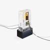
| Penetrator. Image from TE Connectivity. |
TE Connectivity's Josselin Legeay examines the approaches and components of subsea processing necessary to keep brownfield developments operating successfully.
While offshore drilling activity continues to migrate into deeper waters, oil and gas producers are also looking to extend the life of existing brownfield sites. As these sites mature, the challenges of maintaining a profitable flow of hydrocarbons crease is leading producers to use innovative methods to ensure unobstructed flows. A variety of approaches allow subsea processing to keep brownfields operating efficiently and profitably. Subsea systems must be modular to allow practical deployment; wet-mate connectors are important enablers in allowing modules to be connected.
In brownfields, as pressure drops, the water cut increases. As the flow rate decreases, the hydrocarbons are cooled faster by the low seabed temperatures. This can lead to the formation of hydrates on the pipe walls or the mixed water cut freezing. Either can restrict flow and potentially clog the pipe entirely. Hydrate formation is combated by adding inhibitors such as mono ethylene glycol (MEG) in the pipes, heating the pipes to maintain sufficiently high temperatures, and maintaining a sufficient flow pressure. A large quantity of MEG inhibitors are required, which must then be removed topside and recycled for re-injection.
Pipeline heating can be achieved by direct electrical heating (DEH) or pipe-in-pipe heating (PiP). In DEH, a cable laid alongside the pipeline heats the pipe by either conduction or electromagnetic coupling. PiP uses two concentric pipes. The inner pipe carries the hydrocarbons; the annulus (between pipes) contains the heating cable and fiber-based temperature monitor sensors. To maximize the thermal insulation, the annulus is either held at vacuum or filled with an insulating material.
The third way to achieve flow assurance is to separate the different phases and types of flow—gas, oil, water, or solids (sand). Typically, this involves subsea boosting, either through gas compression or subsea pumping. Subsea
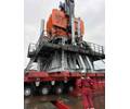
boosting increases the flow rate of the oil or gas to the surface by reducing the back pressure on the well, and therefore increases the recovery factor of the reservoir. For oil, pumping can be used, while natural gases are boosted by compression. Another technique, which can be used in combination with pumping, is to separate the water and oil/gas, injecting the water back into the reservoir to limit pressure drops in the well. This saves energy (the potential energy of getting the water to the topside facility and down again into the well), and it saves a significant amount of space and weight on the heavily-crowded topside facilities. Fig. 1 shows examples of types of subsea processing.
Modularity is key to deploying subsea processing
Moving processing equipment from the platform or shorelines to the seabed creates challenges in its design and deployment. A limiting factor is the weight of such equipment, especially in deep waters. Weight and size issues require that the equipment is designed in a modular fashion, with modules connected together on the sea floor. For example, transformers, circuit breakers, variable-frequency drives, and the final consumers (pump or compressor) all need to be interconnected. Modularity also presents advantages in retrieving, repairing, or upgrading equipment because it is more economical to replace a module than the entire system.
Where several trains of pumps or compressors are in parallel, modularity allows selective shutdown and retrieval of a module, while the other trains continue to boost hydrocarbon production, increasing the overall availability factor of the subsea station. This also eases maintenance by allowing smaller intervention vessels, which are more readily available than high-payload deployment vessels and less costly to operate.
For pipeline heating, wet-mate connectors allow the pipeline to be deployed with its heating elements. The umbilical cable is separately deployed and used to power the system. The wet-mate connectors. Dry-mate connectors are mated topside in dry circumstances and then submerged to their rated depth. They cannot be interconnected on the sea floor. A subsea processing system will involve both dry-mate connectors within a module and wet-mate connectors for intermodule connectivity.
Application of subsea wet-mate connectors is similar to other connector applications—they are used to directly connect two modules or to connect a cable to a module.
A special type of connector is the penetrator, an example of which is shown in Fig. 3. The penetrator is a feed-through connector used to separate chambers from each other or separate a chamber from the outside world. It is basically a bushing designed to accommodate pressure differentials. The inside of a sealed piece of equipment, for example, may be at a significantly different pressure than the surrounding seabed. When possible, subsea modules are pressure balanced—i.e., fluid filled—with the fluid being adjusted at the same sea pressure as outside the module. This allows for thinner walls, reduced weight, and higher reliability as seals are not required to withstand differential pressures. Some modules, such as those containing electronics or other devices such as circuit breakers, cannot withstand pressure higher than atmospheric. Therefore, a penetrator is used to prevent the seawater from leaking into them. On other devices, such as pumps and compressors, which are potentially exposed to the reservoir shut-in pressures, pressure ratings can get up to 15kpsi/1034bars
Penetrators are rated for withstanding pressures—such as 5kpsi, 10kpsi and 15kpsi—which are linked to the reservoir pressure. Required withstanding pressures are related to the fact that the boosting unit is in contact with the hydrocarbons. In case of a shutdown, the whole reservoir pressure may apply to the penetrator.
The penetrator serves an environmentally-important function: an electrical failure would mean a loss of production, but a mechanical failure would release hydrocarbons into the environment.
On other modules not linked to the oil flow, the penetrators are the barrier ensuring the electrical integrity of the module, preventing the modules from being flooded with water.
Wet-mate connectors, then, are key elements allowing cost-effective and technically feasible deployment, while penetrators are essential to preserve the integrity of the complete electrical power supply and to prevent hydrocarbon release into the environment. Specifying wet- mate connectors A high-voltage wet-mate connector is usually specified by the following criteria:
Signal and optical connectors
Wet-mate connectors also provide a means of communications between the control room and the subsea equipment. They enable information retrieval from the sensors located in the well and related subsea equipment to assess the integrity of the well and related equip- ment, optimizing reservoir production. Available for both copper and fiber-optic cables, signal-level connectors serve telemetry and control needs.
Conclusion
Wet-mate connectors are suitable for harsh marine environments. They are a key element of subsea equipment used in the subsea factory processing for oil and gas extraction. They are more complex than standard electrical connectors because of the need to provide a sealed interface that can be maintained at subsea water pressures. Products such as TE’s DEUTSCH line of subsea wet-mate connectors and penetrators are the result of years of off- shore experience, both topside and under- sea. Our product development advantage includes a close working relationship with designers and users of deepwater equipment to best match the connector to application needs, providing for subsea power distribution and processing in a safe, reliable and economical manner.
Josselin Legeay is Product Manager for High Power Systems within TE Connectivity, Global Aerospace, Defense & Marine. Josselin has more than 10 years’ experience with subsea electrical connecters. His areas of expertise include high voltage connectors, connection systems and subsea distribution/collection systems.


